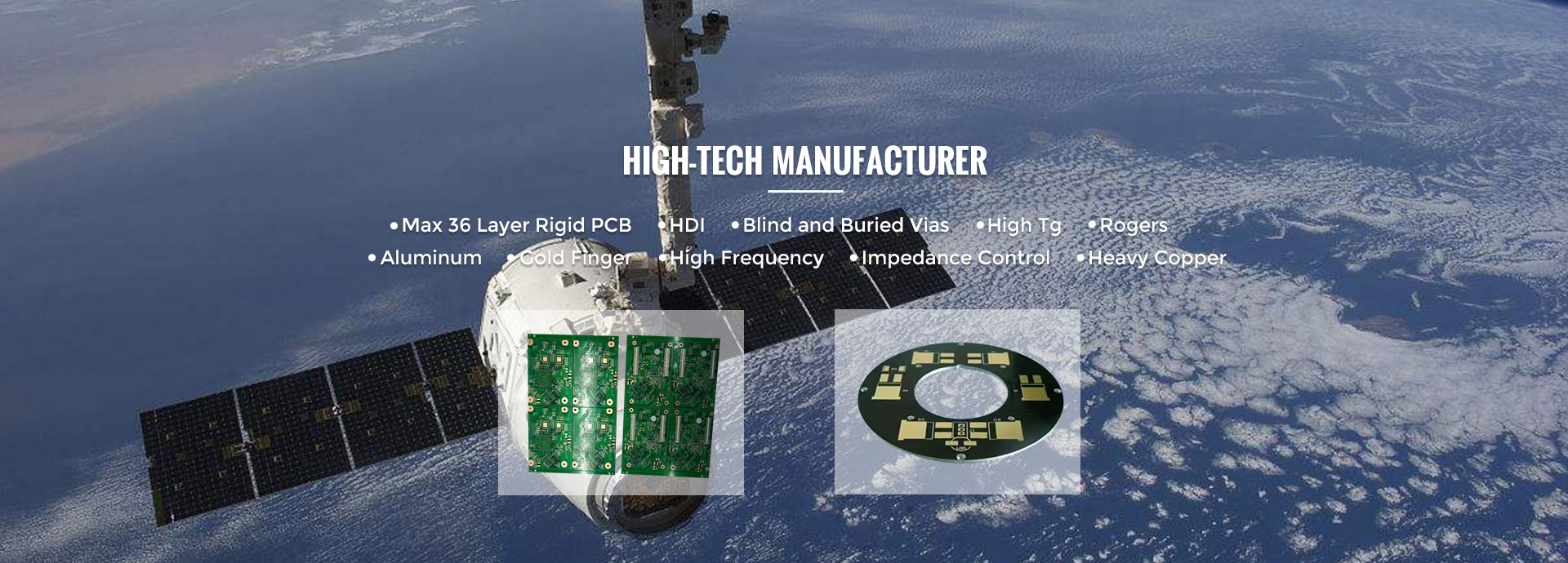
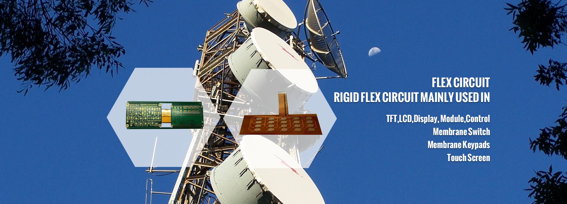
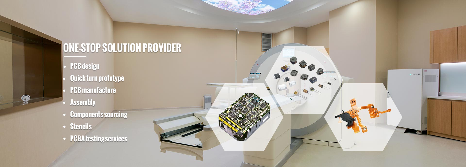
Dear Partners, welcome to MINKINZI – China’s Trusted End-to-End Manufacturing Partner, with 20 years of expertise, we specialize in: Design & Development → Max 58 Layer PCB Fabrication →Turnkey PCBA Assembly → Box-Build Assembly. ODM/OEM/Contract Manufacturing tailored to global standards. Support DFM. Welcome to send your NDA, PCB Gerber, BOM, so that we can provide quotation for you. .
Description :
HDI (High-Density Interconnect) high-frequency hybrid lamination PCBs represent a sophisticated class of advanced interconnect products that merge high-frequency materials with high-speed digital or standard FR-4 substrates onto a single board through a hybrid lamination process. Often referred to as Mixed Dielectric PCB or Hybrid Material PCB constructions, these boards unify the demands of high-frequency signal integrity, high-density routing, and complex structural design into one reliable platform. By leveraging Hybrid Stack-up PCB architecture, manufacturers can combine multiple dielectric families—PTFE, ceramic-filled hydrocarbon, polyimide, and modified epoxy—within a single multilayer build, achieving optimal electrical performance without sacrificing manufacturability or cost efficiency.
HDI high-frequency hybrid lamination PCBs are deployed across a wide spectrum of industries that demand uncompromising signal integrity, mechanical robustness, and high-density routing:
5G communication base stations, millimeter-wave radar (77/79 GHz)
Satellite communication (Ku/Ka bands), phased array antennas
High-speed optical modules (400G/800G/1.6T)
AI accelerator cards, autonomous driving ADAS domain controllers
Medical imaging (MRI, ultrasound), aerospace electronics
High-end test instruments, military electronics
5G AAU (Active Antenna Unit) PCB: A 28-layer board utilizing Rogers RO4350B combined with FR-4 in a hybrid lamination configuration, featuring staggered-via HDI for optimal RF routing density. This High Speed Hybrid PCB structure balances millimeter-wave performance with cost-effective outer layers.
Massive MIMO Base Station RF Board: A 4N+4N hybrid lamination design with PTFE inner layers paired against modified epoxy outer layers. The Mixed Dielectric PCB stack-up ensures low insertion loss for massive MIMO beamforming networks.
77 GHz Millimeter-Wave Automotive Radar PCB: A 6-layer 2-stage HDI board built on Rogers RO3003 paired with Low-Dk FR-4, optimized for the tight impedance tolerances required by automotive FMCW radar sensors.
Sub-6 GHz Small Cell RF Module: An 8-layer 1-stage HDI module using a Taconic Hybrid PCB construction (TLY-5 + FR-4), offering excellent price-performance balance for outdoor small-cell deployments.
Wi-Fi 6E/7 Router Motherboard: A 10-layer 2-stage HDI board leveraging hybrid low-loss dielectric materials to support the wider channel bandwidths and higher modulation schemes of next-generation Wi-Fi.
5G mmWave CPE Terminal PCB: A 12-layer board combining PTFE substrates with Any-layer HDI interconnection, enabling compact, high-performance consumer premises equipment for fixed wireless access.
Satellite Communication Phased-Array Antenna Board: A 20-layer board employing PTFE and high-speed FR-4 hybrid lamination, designed to maintain phase coherence across thousands of radiating elements.
Ka-Band Satellite Communication Terminal PCB: An 8-layer board built on Rogers RT/duroid 5880 laminated with modified FR-4, optimized for high-efficiency Ka-band block up-conversion and down-conversion.
800G Optical Module PCB: A 12-layer 3-stage HDI board featuring PTFE and low-loss FR-4 hybrid lamination to support 800 Gbps PAM4 signaling across pluggable form factors (QSFP-DD, OSFP).
1.6T Optical Module Motherboard: A 16-layer 4-stage HDI board utilizing ultra-low-loss materials to enable the next generation of 1.6 Tbps optical interconnects for hyperscale data centers.
112 Gbps SerDes High-Speed Backplane: A 26-layer board combining Panasonic Megtron hybrid lamination PCB materials with PTFE cores, addressing the extreme signal integrity demands of 112 Gbps PAM4 SerDes channels.
PCIe Gen6 Accelerator Card PCB: A 20-layer 3-stage HDI board built on low-Df dielectric materials, engineered for PCIe Gen6 64 GT/s signaling in AI training and inference accelerators.
AI Training GPU Module Board: A 24-layer 4N+4N+4N HDI board featuring an ultra-low-loss core, providing the signal and power integrity backbone for large-scale GPU clusters.
High-Port-Count Network Switch Motherboard: A 22-layer Hybrid Material PCB with a hybrid dielectric constant core board, supporting 256/512 ports of 800G/1.6T Ethernet switching.
CPO (Co-Packaged Optics) Module Substrate: A 12-layer board combining PTFE with low-loss thermoset material to support the close integration of optical engines and switch ASICs.
Autonomous Driving Central Domain Controller PCB: A 16-layer 3-stage HDI board built on hybrid low-Dk dielectric materials, consolidating ADAS, cockpit, and chassis functions onto a single high-performance platform.
4D Imaging Radar Motherboard: A 12-layer 2-stage HDI board combining PTFE with high-speed FR-4, supporting elevation measurement in addition to traditional range, velocity, and azimuth.
Smart Cockpit Main Control PCB: A 14-layer 3-stage HDI board using Hybrid Stack-up PCB construction with hybrid dielectric materials to drive multi-display infotainment and AI-enabled HMI.
T-Box V2X Communication Module: An 8-layer 2-stage HDI board combining low-loss substrates with FR-4, enabling reliable vehicle-to-everything (V2X) communications in C-V2X and DSRC bands.
BMS High-Frequency Sampling Board: A 10-layer 1-stage HDI board for battery management system high-frequency current and voltage sampling in high-voltage EV powertrains.
Automotive LiDAR Mainboard: A 12-layer 3-stage HDI board combining PTFE with Low-Dk FR-4, designed to handle the wide bandwidth and high dynamic range of automotive LiDAR receivers.
MRI RF Coil PCB: A 6-layer board combining PTFE with ceramic filled PCB material to achieve the precise dielectric stability required in high-field magnetic resonance imaging coils.
Industrial CT High-Frequency Sampling Board: A 10-layer 1-stage HDI board optimized for high-speed analog-to-digital sampling in industrial computed tomography scanners.
Medical Endoscope Image Processing Board: A 12-layer 3-stage HDI board utilizing hybrid dielectric materials to deliver high-resolution image processing in minimally invasive surgical systems.
High-End Oscilloscope Analog Front-End PCB: A 14-layer 2-stage HDI board with low-Dk dielectric materials, supporting multi-GHz analog front-end bandwidth in real-time oscilloscopes.
Semiconductor ATE Tester Mainboard: A 20-layer 3-stage HDI board built on hybrid high-speed materials to provide the precision timing and signal fidelity required by automatic test equipment.
Airborne Radar T/R Module PCB: A 16-layer board combining PTFE with low-loss modified epoxy, engineered for transmit/receive modules in fighter and surveillance radar systems.
Electronic Warfare Signal Processing Board: A 20-layer 3-stage HDI board using hybrid low-loss materials for broadband digital signal processing in electronic countermeasures.
Spaceborne Phased-Array Antenna Feed Network PCB: A 14-layer board built on Rogers combined with modified FR-4, qualified for the thermal and outgassing requirements of low-earth orbit and geostationary platforms.
Military Phased-Array Communication Mainboard: A 22-layer 4-stage HDI board with a multi-material high-frequency hybrid stack-up, supporting secure, anti-jam tactical communications.
A qualified manufacturer should demonstrate proven ability to process a broad range of high-frequency materials, including Rogers, PTFE, Taconic, Isola, Panasonic Megtron, polyimide, ceramic-filled laminates, and low-loss FR-4. Look for in-house Isola High Frequency PCB material handling experience and the capability to support a true Megtron Hybrid Lamination PCB build with PPO, modified epoxy, and PTFE layers in a single stack-up. Equally important are robust material re-inspection and failure analysis (FA) workflows, plus stable material supply channels backed by Long-Term Agreements (LTAs) with primary CCL vendors.
Hybrid lamination experience at stack-up complexities of 3N+3N and beyond is essential, as is laser drilling precision at ≤ 75 μm micro-via diameters. The manufacturer must demonstrate tight control of plating uniformity and via-wall roughness (Ra ≤ 0.5 μm), full via-filling plating capability for stacked and staggered micro-via arrays, and impedance tolerance control of ±5% to ±7% across the entire panel. Process maturity for Taconic Hybrid PCB, PTFE-FR4 co-lamination, and polyimide hybrid PCB constructions is a strong indicator of true hybrid expertise.
Look for an engineering team that provides comprehensive DFM/DFA reviews, SI/PI simulation assistance (HFSS, SIwave), impedance modeling, and stack-up design recommendations. The ability to perform failure analysis using cross-sectioning, scanning acoustic tomography (SAT), and time-domain reflectometry (TDR) is a clear differentiator.
Certifications such as IATF 16949 (Automotive), AS9100 (Aerospace), ISO 9001, ISO 14001, and UL provide a strong baseline of quality system maturity. Verify that the production line is equipped with AOI, ICT, impedance testing, X-ray, and flying probe testers, and that the manufacturer can document lot-level traceability and reliability test data.
The right partner must offer flexibility for both high-mix/low-volume NPI runs and high-volume mass production, with proven support capabilities for overseas customers across languages, time zones, and logistics. A sustained On-Time Delivery (OTD) rate of ≥ 95% is a useful benchmark of operational discipline.
A transparent cost structure covering both NRE and mass-production unit pricing, combined with strict IP confidentiality protocols (NDAs, isolated production lines, encrypted file transfer), is essential when sharing sensitive designs.
Comprehensive Material Database
Minkinzi has established long-term partnerships with leading material suppliers such as Rogers, Taconic, Isola, Panasonic, Doosan, and Shengyi. We have built an application database covering over 50 high-speed and high-frequency materials—including PTFE, PPO, modified epoxy, ceramic-filled laminates, low-loss FR-4, and Polyimide Hybrid PCB cores—enabling us to deliver optimal stack-up solutions tailored to specific combinations of Dk, Df, Tg, and CTE. Our expertise spans Low DK DF PCB design principles and High Speed Hybrid PCB material selection, with validated solutions for Ceramic Filled PCB, PTFE-FR4, and hydrocarbon-ceramic stack-ups.
Leading Hybrid Lamination Process
Minkinzi has achieved mass production of 2N+2N, 3N+3N, and 4N+4N hybrid lamination configurations, with lamination thickness tolerance control of ±25 μm. We have developed proven solutions for challenges such as CTE mismatch, delamination, and blistering between PTFE, polyimide, ceramic-filled, and FR-4 dielectrics, and we mass-produce Hybrid Material PCB constructions up to 30 layers. Our Hybrid Stack-up PCB expertise covers Rogers, Taconic, Isola, Megtron, and ceramic-filled material combinations.
Advanced HDI Micro-via Technology
We support a minimum laser drilling diameter of 50 μm (2 mil), with mass production capability for Any-layer HDI. Our process includes single-step formation of stacked and staggered via plating and filling, with via position accuracy of ±15 μm.
High-Frequency Signal Integrity Assurance
Impedance control accuracy of ±5% (industry-leading), full-process TDR testing, and SAT scanning are standard. We collaborate with customers on HFSS and SIwave simulation and correlation verification, and we maintain testing capabilities across multiple frequency bands (10 GHz–77 GHz) to validate every Mixed Dielectric PCB build.
Proven Mass Production Track Record
Minkinzi has mass-produced HDI hybrid lamination products—including 5G base stations, mmWave radars, 800G optical modules, and AI accelerator cards—for customers in over 30 countries. We have delivered more than 2 million HDI hybrid lamination PCBs to date, with specifications up to 28 layers, 4N+4N lamination, and maximum dimensions of 24"×36". Our portfolio covers Isola High Frequency PCB, Taconic Hybrid PCB, Megtron Hybrid Lamination PCB, and Polyimide Hybrid PCB solutions across all major end markets.
Comprehensive Quality and Certifications
Minkinzi is certified to IATF 16949, AS9100D, ISO 9001, ISO 14001, and UL standards. Our production lines are equipped with fully automated AOI, X-ray, impedance testers, and flying probe testers, and we maintain a stable yield rate exceeding 98.5%.
Contact Minkinzi factory to manufacture your HDI high-frequency hybrid lamination PCBs: Email: sales@minkinzi.com
Applications :
HDI PCB | High-Frequency PCB | Hybrid Lamination PCB | 5G Communication PCB | Millimeter-Wave Radar PCB | Satellite Communication PCB
HDI High-Frequency Hybrid Lamination PCBs represent the pinnacle of advanced circuit board engineering, seamlessly integrating premium high-frequency materials—including Rogers RO4350B, RO4003C, RO3003, Taconic TLG/TLY series, PTFE-based substrates, Arlon, and Isola high-speed materials—with industry-standard FR-4 dielectrics within a unified multilayer architecture. Through a meticulously controlled hybrid lamination stack-up process, these boards deliver exceptional high-frequency signal transmission performance alongside the high-density interconnect (HDI) routing capabilities demanded by next-generation electronic systems.
The proprietary Hybrid Lamination Stack-up methodology enables the combination of two or more dielectric systems within a single board, allowing designers to place high-frequency signal layers adjacent to low-cost FR-4 power and control layers. This balanced architecture is the foundation of innovation across 5G/6G communications, millimeter-wave radar, satellite communications, automotive ADAS, aerospace & defense, and high-performance computing platforms.
As a leading manufacturer, Minkinzi specializes in producing Sequential Lamination PCB structures that combine microvia HDI technology with low-loss high-frequency laminates, enabling our customers to achieve superior signal integrity, reduced insertion loss, and unmatched design flexibility for the most demanding RF and microwave applications.
To meet the diverse complexity requirements of modern electronic systems, Minkinzi offers a comprehensive portfolio of HDI High-Frequency Hybrid Lamination PCB configurations across multiple layer counts and HDI architectures.
4-Layer HDI Hybrid PCB — Ideal for compact RF front-end modules, Wi-Fi 6E/Wi-Fi 7 routers, and simple 5G small cell/femtocell units, the 4-Layer HDI Hybrid PCB delivers an optimal balance of performance and cost-efficiency for moderately complex designs. This configuration typically features a 1+N+1 or 2+2 HDI structure, making it the preferred choice for miniaturized wireless products where board real estate is at a premium.
6-Layer HDI Hybrid PCB — The 6-Layer HDI Hybrid PCB is the workhorse configuration for mid-complexity designs including 5G mmWave base station antennas, RF front-end modules (FEM), automotive mmWave radar (77/79 GHz) front-ends, and ADAS central control units. With enhanced routing capacity and improved power distribution, this layer count supports 2+4+2 or 3+3+3 stack-ups with Blind and Buried Via PCB architectures.
8-Layer HDI Hybrid PCB — Engineered for sophisticated applications such as phased array antennas, optical transceivers (QSFP-DD / OSFP), V2X communication modules, and avionics flight control systems, the 8-Layer HDI Hybrid PCB supports Any-Layer HDI PCB interconnect topologies. This configuration enables complex power plane segmentation, multiple ground reference layers, and dedicated high-frequency signal routing channels.
10-Layer HDI High Frequency PCB — The 10-Layer HDI High Frequency PCB is engineered for the most demanding applications, including military surveillance radar, electronic warfare (EW) jamming systems, missile guidance and seeker heads, AI accelerator cards (GPU/TPU modules), and high-performance computing (HPC) motherboards. Supporting 100+ Gbps signal lanes and complex multi-zone impedance profiles, this configuration represents the cutting edge of high-frequency PCB engineering.
Microvia HDI PCB Technology — At the core of our high-density interconnect capability, Microvia HDI PCB technology enables laser-drilled blind vias with diameters as small as 50μm (2mil), supporting ultra-fine pitch BGA packages and miniaturized RF components. Minkinzi's precision CO₂ and UV laser systems achieve microvia diameter accuracy of ±25μm with hole position accuracy of ±25μm and hole wall roughness Ra ≤ 25μm.
Stacked Via HDI PCB Construction — Stacked Via HDI PCB designs enable vertical signal pathways between multiple layers through directly stacked microvias, dramatically increasing routing density in Any-Layer HDI PCB configurations. Minkinzi's optimized plating chemistry ensures reliable copper fill within stacked vias, with barrel copper thickness ≥ 25μm and dimple depth ≤ 15μm, achieving plating uniformity Cp values ≥ 1.33.
Blind and Buried Via PCB Engineering — Blind and Buried Via PCB architectures maximize routing channels while minimizing surface real estate consumption. Our sequential build-up process supports complex via structures including via-in-pad plated over (VIPPO), back-drilled stubs, and depth-controlled drilling for high-speed signal via optimization.
Any-Layer HDI PCB Interconnect — Any-Layer HDI PCB (also known as ALIC—Any-Layer Interconnect) represents the most advanced HDI topology, where every layer pair is interconnected through stacked microvias. This architecture is essential for the most complex designs including 5G mmWave base station antennas with beamforming arrays, AI accelerator cards, and high-performance computing motherboards requiring 400G/800G data interconnects.
Sequential Lamination PCB Process — The Sequential Lamination PCB process enables the construction of complex multi-material stack-ups through multiple (2–3+) lamination cycles. This approach is fundamental to creating Hybrid Lamination Stack-up designs that combine high-frequency materials (PTFE, Rogers, Taconic) with FR-4 cores, allowing each material to be optimized for its specific function within the overall signal path.
High-Frequency Material Portfolio — A qualified HDI High-Frequency Hybrid Lamination PCB manufacturer must demonstrate reliable processing capability across the full spectrum of industry-leading high-frequency materials, including Rogers (RO4350B, RO4003C, RO3003, RO3010), Taconic (TLG, TLY, RF-35), PTFE-based substrates, Arlon, and Isola high-speed materials. Support for at least 5–8 mainstream international brands ensures flexibility in addressing diverse customer design requirements and application scenarios.
Hybrid Lamination Process — The facility must demonstrate validated capability for multiple (2–3+) hybrid lamination cycles combining high-frequency materials with FR-4 substrates. The process must reliably produce complex multi-material structures such as Rogers + FR4 + Rogers, PTFE + FR4, Taconic + FR4, and any combination of ceramic-filled hydrocarbon laminates with standard epoxy systems. This Sequential Lamination PCB expertise is critical for achieving the Hybrid Lamination Stack-up architectures demanded by modern high-frequency designs.
Material Inventory Management — Maintenance of a 30–60 day safety stock for core high-frequency materials is essential to prevent delivery delays and ensure supply chain resilience. Strategic inventory of bonding sheets, prepregs, and copper-clad laminates from multiple manufacturers provides flexibility in accommodating urgent customer requirements.
Supply Chain Certification — Direct authorized distributorships with manufacturers like Rogers, Taconic, Isola, and Arlon guarantee material traceability and authentic sourcing. Material certificates of analysis (COA) must be archived for every production lot, ensuring full compliance with customer specifications and industry standards.
HDI Layer Capability — The facility must possess Any-Layer HDI PCB (3rd-order/Any-Layer Interconnect) production capabilities, supporting laser-drilled blind vias, buried vias, stacked microvias, and complex via-in-pad structures. Both CO₂ laser (for organic dielectrics) and UV laser (for high-frequency ceramic-filled materials) capabilities are required to achieve microvia diameters ≤ 75μm (3mil), with some high-end products requiring 50μm (2mil) capability.
Trace Width/Spacing Precision — Stable production of fine circuitry below 3mil/3mil (75μm) is required, with high-end products demanding 2mil/2mil capability. This fine-line capability is essential for the 100Ω differential and 50Ω single-ended impedance structures used in high-speed digital and RF applications.
Layer Count and Board Thickness — Support for 4–20 layer hybrid high-frequency structures is required, with board thickness tolerance maintained at ±10%. This includes the ability to produce 4-Layer HDI Hybrid PCB, 6-Layer HDI Hybrid PCB, 8-Layer HDI Hybrid PCB, and 10-Layer HDI High Frequency PCB configurations with consistent quality and reliability.
Impedance Control Precision — Impedance control capability of ±5% (with ±8% acceptable for specific applications) must be supported by TDR (Time Domain Reflectometry) testing equipment and validated Polar Si8000/Si9000 field solver simulations. Each production lot requires 100% impedance test coverage with SPC (Statistical Process Control) charts maintained for continuous process improvement.
Special Processes — Advanced capabilities including back drilling for stub elimination in high-speed vias, depth-controlled drilling for partial-depth blind vias, via-in-pad plated over (VIPPO) for BGA breakout optimization, and controlled-depth routing are essential for modern high-frequency PCB designs.
Quality Management System Certifications — A qualified manufacturer must maintain current certifications including ISO 9001:2015 (basic quality system), IATF 16949:2016 (mandatory automotive industry certification for automotive customers), AS9100D (aerospace certification for defense and aviation customers), ISO 13485:2016 (medical industry certification for medical device customers), and UL Certification (94V-0 flame retardant rating for safety compliance).
Environmental Certifications — Full compliance with RoHS, REACH, and HF (Halogen-Free) directives is required to meet global environmental regulations and customer sustainability requirements. Material declarations and compliance documentation must be readily available for every shipment.
Military-Grade Confidentiality — For defense clients, weapon and equipment quality management system certification, confidentiality qualifications, and secure facility clearances may be required. Manufacturers must demonstrate robust document control, secure data handling, and personnel security protocols.
DFM Collaborative Design — Complimentary DFM (Design for Manufacturability) reviews assist clients in optimizing designs for manufacturability, reliability, and cost-efficiency. Experienced application engineers provide stack-up recommendations, material selection guidance, and impedance design support from concept through production.
Engineering Response Speed — Standard DFM feedback must be provided within 8–12 hours, with urgent requests acknowledged within 4 hours. Rapid response engineering support is critical for time-sensitive development programs and competitive product launches.
NDA (Non-Disclosure Agreement) — Willingness to sign strict technical confidentiality agreements and possession of robust document and data confidentiality management systems protect customer intellectual property throughout the design and manufacturing cycle.
Flexible Small-Batch Support — Support for rapid prototyping orders starting from 5–10 square meters enables customers to validate designs quickly and iterate efficiently before committing to volume production. Quick-turn prototype services with 5–7 day lead times accelerate time-to-market for new product introductions.
The fundamental challenge in Hybrid Lamination Stack-up construction lies in managing the significant CTE (Coefficient of Thermal Expansion) mismatch between high-frequency materials and standard FR-4 substrates. PTFE-based resins, for example, exhibit Z-axis expansion characteristics dramatically different from epoxy-based FR-4 systems, leading to inconsistent thermal expansion after hybrid lamination. This mismatch creates susceptibility to reliability issues such as delamination, open circuits, and short circuits under thermal shock conditions. The solution requires mastery of multi-material lamination profile optimization, precise bonding sheet selection, and carefully controlled pre-cure processes that account for the unique thermal characteristics of each dielectric system.
Achieving consistent microvia quality across diverse material types presents ongoing challenges. High-frequency materials exhibit varying laser ablation energy absorption rates, requiring precise coordination between CO₂ lasers (optimized for organic dielectrics) and UV lasers (better suited for ceramic-filled high-frequency materials). The microvia diameter requirements of ≤ 75μm (3mil)—with some applications requiring 50μm—demand exceptional laser system precision, with hole diameter accuracy maintained at ±25μm, hole position accuracy at ±25μm, and hole wall roughness Ra ≤ 25μm. This Microvia HDI PCB capability is foundational to all advanced HDI architectures including Stacked Via HDI PCB and Any-Layer HDI PCB designs.
Ensuring reliable copper plating within stacked microvias during Any-Layer Interconnect (ALIC) processes is one of the most demanding technical challenges in Stacked Via HDI PCB manufacturing. The difficulty in achieving adequate plating solution exchange within the small volumes of stacked vias can result in voids, insufficient copper thickness, or plating defects. Key control parameters include plating uniformity Cp value ≥ 1.33, barrel copper thickness ≥ 25μm, and dimple depth ≤ 15μm, with advanced pulse plating chemistries and optimized solution agitation systems employed to ensure consistent results.
The Dielectric Constant (Dk) of high-frequency materials is significantly affected by operating frequency, temperature, and humidity, creating challenges for maintaining consistent impedance values across production lots and operating environments. Precision requirements include 100Ω differential impedance tolerance of ±10% and 50Ω single-ended impedance tolerance of ±10%. Effective control requires establishment of comprehensive material Dk/Df databases, use of field solver simulation tools such as Polar Si8000/Si9000, and implementation of SPC control charts for all impedance-critical features.
PTFE and ceramic-filled high-frequency materials present unique processing challenges, particularly in drilling and hole-wall metallization. Traditional brown oxide treatment used prior to chemical copper deposition is ineffective on PTFE surfaces due to their chemical inertness. Plasma etching is required to achieve adequate hole-wall roughening and surface activation for reliable electroless copper deposition. Specialized sodium etchants or plasma treatment systems are necessary to ensure proper copper adhesion and long-term reliability.
High-layer-count mixed-material boards (12+ layers) are particularly prone to warpage during the lamination and cooling cycles due to the differential shrinkage rates of dissimilar materials. Control targets include warpage ≤ 0.75% per IPC-6012 Class 3 standard, with high-end customer requirements demanding ≤ 0.5%. Symmetrical stack-up design, balanced copper distribution, and controlled cooling profiles are essential to achieving these stringent flatness requirements.
Copper foil surface roughness (Rz) and etching factor (D-Factor) directly impact high-frequency signal insertion loss, making surface treatment a critical quality parameter. Key performance metrics include insertion loss deviation ≤ 0.5 dB/inch at 28 GHz for millimeter-wave applications. Low-profile (LP) and very-low-profile (VLP) copper foils with Rz values < 2μm are specified for the most demanding signal integrity requirements.
The significant differences in glass transition temperature (Tg), curing pressure requirements, and heating rate compatibility among different materials create a narrow overall process window for mixed-material lamination. Establishment of a refined process parameter system for sequential lamination—including ramp rates, dwell times, pressure profiles, and cooling curves—is essential for achieving reliable Hybrid Lamination Stack-up results. Each material combination requires individualized process development and validation.
High-Frequency Material Verification — Every lot of incoming high-frequency material is re-tested for Dk and Df values using resonant cavity or split-post dielectric resonator methods, with material certificates of analysis (COA) archived for full traceability. Materials failing to meet published specifications are rejected and quarantined to prevent inadvertent use in production.
Copper Foil Thickness — Customer-specified copper foil thickness tolerances are verified to ±5% using precision micrometers and X-ray fluorescence (XRF) coating thickness gauges. Both electrodeposited (ED) and rolled-annealed (RA) copper foils are inspected for surface quality and profile characteristics.
Prepreg (PP) Control — Strict control of resin content (RC%), gel time, and flow characteristics ensures consistent dielectric layer thickness and bonding performance. Prepreg shelf life is monitored and materials are used on a first-in-first-out (FIFO) basis to prevent aged material usage.
Bonding Sheet Verification — Bonding sheet thickness and resin content are matched to design requirements and verified upon receipt. For hybrid stack-ups, bonding sheet compatibility with adjacent high-frequency materials is confirmed through adhesion testing.
First Article Inspection (FAI) — Metallographic cross-section analysis is required for the first unit of every production batch to verify trace width, hole wall copper thickness, plating uniformity, and dielectric layer thickness. FAI reports document compliance with all design specifications and are reviewed by engineering before production release.
AOI (Automated Optical Inspection) — Equipped with high-resolution AOI systems featuring 5μm inspection precision, 100% full inspection is performed on all inner and outer layers. Defect detection algorithms identify opens, shorts, copper voids, and pattern deviations for immediate rework or scrap decisions.
Impedance Testing (TDR) — 100% impedance test coverage is maintained using calibrated TDR equipment, with SPC control charts established for all impedance-critical features. Coupon-based testing is supplemented by in-circuit impedance verification on production boards.
X-Ray Drilling Inspection — Blind via alignment accuracy is verified to within ±50μm using precision X-ray inspection systems. Layer-to-layer registration is monitored continuously to detect drift and enable real-time process correction.
Micro-Section Analysis — Random sampling of longitudinal cross-sections per production batch verifies hole wall copper thickness, plating layer uniformity, dielectric spacing, and overall stack-up structure. Photomicrographs are archived for quality records and customer documentation.
Reliability Testing Capabilities — Comprehensive reliability testing is performed to validate long-term performance under accelerated stress conditions:
Thermal Stress Test: 288°C/10 seconds/3 cycles — no delamination, no blistering
IST (Interconnect Stress Test): Thermal cycling resistance for via and trace reliability
TCT (Thermal Cycling Test): -55°C to +125°C / 1000 cycles for temperature extremes
Solderability Test: Per IPC J-STD-003 for component assembly compatibility
Ionic Contamination Test: ≤ 1.56 μg NaCl/in² for cleanliness verification
Adhesion Test: Cu-Peel Strength ≥ 1.05 N/mm for copper-to-substrate bond integrity
Appearance and Dimensions — 100% visual inspection is performed under controlled lighting conditions, with dimensional measurement using calibrated CMM (Coordinate Measuring Machine) systems for critical features.
Documentation and Traceability — Each board is assigned a unique trace code enabling complete traceability back to the material batch, production equipment, operator, and process parameters. This traceability supports rapid root cause analysis and continuous improvement initiatives.
Cpk Capability Index — Critical dimensions maintain Cpk ≥ 1.33, with impedance-critical features achieving Cpk ≥ 1.67. Cpk data is monitored continuously and reviewed in monthly quality performance reviews.
8D Reporting Mechanism — A preliminary 8D (Eight Disciplines) report for quality anomalies is submitted within 24 hours of detection, with final root cause analysis and corrective action implementation achieved within 5 working days. The 8D process ensures systematic problem resolution and prevention of recurrence.
Minkinzi stands as your trusted partner for the most demanding HDI High-Frequency Hybrid Lamination PCB requirements. Our comprehensive capabilities span the full spectrum of 4-Layer HDI Hybrid PCB, 6-Layer HDI Hybrid PCB, 8-Layer HDI Hybrid PCB, and 10-Layer HDI High Frequency PCB configurations, all manufactured with the precision and reliability that mission-critical applications demand.
Our engineering team brings decades of combined experience in Hybrid Lamination Stack-up design and Sequential Lamination PCB manufacturing, supported by state-of-the-art Microvia HDI PCB, Stacked Via HDI PCB, Blind and Buried Via PCB, and Any-Layer HDI PCB production capabilities. Whether your application involves 5G mmWave base station antennas, autonomous driving domain controllers, AI accelerator cards, or satellite communication terminals, Minkinzi delivers the quality, consistency, and innovation that drives your products to market success.
Contact Minkinzi today to discuss your HDI High-Frequency Hybrid Lamination PCB requirements. Our engineering team is ready to provide DFM support, material recommendations, and rapid quotations for your next project.
Flow Chart :
HDI (High-Density Interconnect) high-frequency hybrid PCBs serve as the core platform for 5G communications, millimeter-wave radar, satellite communications, aerospace applications, and high-end testing equipment. As a trusted manufacturer of Impedance Controlled HDI PCB and High Frequency Signal PCB solutions, Minkinzi laminates premium high-frequency materials (such as Rogers RO4350B, RO4003C, PTFE, or ceramic-filled hydrocarbon substrates) with FR-4 to deliver the required high-frequency electrical performance while balancing cost, mechanical strength, and manufacturability.
Our expertise spans 5G HDI Hybrid PCB designs, 77GHz Radar PCB modules, and Millimeter Wave PCB assemblies — engineered to meet the most demanding signal integrity requirements across global industries.
HDI PCB for 5G Base Station: 1–3 stage HDI and any-layer HDI interconnection architectures
HDI PCB for Aerospace: Precision line width/spacing down to 2.5 mil/3 mil (63.5 μm)
HDI PCB for Automotive Radar: Minimum laser blind via diameter of 75 μm
HDI PCB for Satellite Communication: Mixed-lamination layer count from 4–30 layers with maximum board thickness of 6.0 mm
RF PCB for Telecommunications: Industry-leading dielectric constant (Dk) tolerance of ±2% (@10 GHz) paired with ultra-low dissipation factor (Df)
This initial stage forms the "first mile" that determines overall project success. Upon receiving design files such as Gerber, ODB++, or IPC-2581, our engineering team conducts a systematic evaluation to ensure manufacturability of your High Frequency Signal PCB or RF PCB for Telecommunications.
Our engineering team executes rigorous preparation to ensure that every Impedance Controlled HDI PCB and Millimeter Wave PCB meets exacting performance standards.
Material Procurement & Incoming Inspection
Verification of high-frequency laminate batch numbers, dielectric parameters (Dk/Df), and Td (decomposition temperature)
Impact of copper foil roughness on insertion loss (HVLP3 or RTF low-roughness copper foil recommended)
Laminate storage environment: Temperature 20–25°C, Humidity ≤55% RH
CAM Compensation and Registration Accuracy
Registration accuracy for mixed-material boards directly impacts interlayer interconnection reliability; target: ±25 μm
LDI (Laser Direct Imaging) exposure compensation values must be set individually based on material properties
Step compensation is prioritized for high-frequency regions to mitigate uneven etching
Lamination Stack-up Design
Symmetrical stack-up of high-Tg FR-4 (Tg ≥ 150°C) and high-frequency core materials
Optimized prepreg (PP) resin flow to prevent resin starvation or excessive resin bleed-out in high-frequency zones
This critical stage validates process feasibility for 5G HDI Hybrid PCB and 77GHz Radar PCB designs through four core manufacturing steps.
Brown Oxide Treatment: Horizontal brown oxide line with oxide film thickness controlled at 0.8–1.5 μm
Exposure & Development: LDI laser exposure with energy 25–45 mJ/cm² (adjusted based on material)
Etching: Acidic cupric chloride etching with line width tolerance ±0.025 mm
AOI Inspection: 100% automated optical scanning with defect classification and logging
CO₂ vs. UV Laser Selection:
High-frequency PTFE/Ceramic materials: UV laser (355 nm) preferred to avoid carbonization
FR-4 and PP: CO₂ laser is sufficient
Key Parameters: Pulse energy, frequency, defocus value, and assist gas (nitrogen to prevent oxidation)
Hole Size Control: Target 75–100 μm blind vias with positional accuracy ±15 μm
Hole Quality: No carbon residue on hole walls; no residual resin at hole bottoms
Plasma Treatment (Essential for high-frequency materials): CF₄ + O₂ gas mixture to activate hole walls
Electroless Copper Deposition: Copper thickness ≥0.3 μm; backlight test rating of Level 10 (pass)
Hole Copper Integrity: Metallographic cross-section inspection with no hole-wall separation or plating voids
Plated Copper Thickness: Surface copper 25–35 μm; barrel copper 20–25 μm
Plating Uniformity: Achieved via pulse plating or VCP (Vertical Continuous Plating) lines
Impedance Control: Precise control using ultra-thin copper foil (1/3 oz–1/2 oz) combined with etch compensation
High-Frequency Trace Design: Avoid right-angle traces; use arcs or 45° corners to minimize signal reflection — critical for every HDI PCB for 5G Base Station and HDI PCB for Aerospace application
Lamination represents the core process challenge for high-frequency mixed-material boards and HDI PCB for Satellite Communication designs.
First-Stage HDI: One lamination cycle combined with one laser drilling cycle
Second-Stage HDI: Two lamination cycles with two laser drilling cycles (requires via filling via electroplating or copper paste)
Third-Stage HDI: Three lamination cycles requiring planarization via electroplating (stacked vias / staggered vias)
Blistering/Delamination: HF materials have low surface energy; plasma or chemical roughening is required prior to brown oxide treatment
Excessive Z-Axis Expansion: Select low-CTE PP (e.g., Hitachi MCL-E-679) or PP compatible with HF materials
Resin Flow Contamination in HF Areas: Use resin-blocking tape or window-opening designs
Once samples pass all validations, the process transitions into mass production preparation for your HDI PCB for Automotive Radar or RF PCB for Telecommunications program.
Process Freeze & NPI Documentation Package
Complete MI (Manufacturing Instructions), Work Instructions, and Inspection Standards
Cpk analysis report for critical parameters (Target Cpk ≥ 1.33)
FAI (First Article Inspection) report signed and archived
Small-Batch Validation
Simultaneous trial production across multiple machines and lines to verify process consistency
Implementation of SPC (Statistical Process Control) for real-time monitoring of critical dimensions
Mass Production Ramp-Up
Capacity planning, identification of bottleneck stations, and automation upgrades
Establishment of OEE (Overall Equipment Effectiveness) dashboard (Target ≥ 85%)
Outgoing Quality Assurance
100% electrical testing (flying probe and fixture), including open/short circuits, insulation resistance, and dielectric strength
Impedance testing with 100% TDR testing for high-frequency items
Dual-layer inspection combining AOI with manual visual inspection
X-ray inspection for BGA/QFN pad alignment
Cross-section metallographic analysis (batch sampling for barrel copper thickness and interlayer adhesion)
PPAP/APQP documentation (mandatory for automotive-grade clients)
Customer feedback 8D closed-loop process with 24-hour response time
Annual process review for cost optimization and yield improvement (mass production yield target ≥ 95%)
Material traceability system with unique QR code per board for full-process traceability
Whether you are developing a 5G HDI Hybrid PCB for next-generation base stations, a 77GHz Radar PCB for advanced driver-assistance systems (ADAS), a Millimeter Wave PCB for aerospace and defense applications, or a High Frequency Signal PCB for satellite communications, Minkinzi delivers the engineering precision, process rigor, and manufacturing scale your program demands.
Our Impedance Controlled HDI PCB solutions and RF PCB for Telecommunications platforms are trusted by global engineers who refuse to compromise on signal integrity, reliability, or time-to-market.
Contact Minkinzi today for HDI High-Frequency Hybrid Lamination PCB manufacturing: Email: sales@minkinzi.com
Capability :
A factory capable of stable mass production of high-end HDI high-frequency hybrid-lamination PCBs is far from a typical PCB manufacturer. It must meet strict prerequisites across every dimension of design, materials, and process control. As a leading HDI High Frequency PCB Supplier and Custom Hybrid Lamination PCB Factory, Minkinzi fully meets and exceeds these standards, standing as one of the few high-end PCB manufacturers in China capable of stable, volume delivery of complex hybrid-lamination HDI high-frequency boards. Our capabilities are built around the most demanding applications, from automotive radar and 5G base stations to Hybrid Lamination PCB for Defense systems, AI servers, and High Frequency PCB for Medical Equipment.
These thresholds define our baseline. Every board we produce — whether destined for Hybrid PCB for Radar Systems, Microwave PCB for Wireless infrastructure, or HDI PCB for IoT Devices — is built to meet or surpass them.
Our advanced drilling infrastructure supports the smallest geometries demanded by today's high-frequency designs. Laser Drilling (CO₂ / UV dual-station) delivers 3-mil microvias with positional accuracy of ±0.05 mm — essential for HDI PCB for Military Applications and aerospace-grade products. Mechanical Drilling handles minimum 6-mil holes with stack-up capability of up to 8 panels. Plasma Desmear ensures deep-hole plating capability, with barrel copper thickness of ≥25 μm. Back-drilling Technology reduces stub effects, controlling signal integrity for high-speed serial links operating at 56 Gbps, 112 Gbps PAM4, and beyond.
We deploy LDI (Laser Direct Imaging) for trace width tolerance of ±10%, and SAP / mSAP processes that support 2-mil fine-line circuitry. Our Solder Mask Dam capability reaches 3 mils, with the ability to open beneath the dam. Vacuum Lamination further enhances fine-line pattern precision, ensuring repeatable results for any-layer HDI and high-density interconnect designs used in HDI PCB for Data Center switching platforms and High Frequency PCB for Antenna modules.
Our Multi-stage Sequential Lamination supports complex structures up to 4N+4N+4N + Core. We bring deep Mixed-Material Experience across FR4 (Tg135/Tg150/Tg170), Rogers 4350B / 4003C / RO3003, and RT/duroid 5880. Lamination thickness tolerance is held to ±0.05 mm (inter-layer) and ±10% (overall board). Tight Resin Flow Control prevents high-frequency layer resin from encroaching into circuit areas and degrading Dk performance — a critical factor for any Microwave PCB for Wireless front-end module.
We offer a complete portfolio of surface finishes: ENIG / ENEPIG / OSP / Immersion Tin / ENIG + OSP. For mixed-signal boards, we provide Selective ENIG + OSP, applying ENIG to high-frequency pads and OSP to solder mask areas. ENIG Thickness Control is held to 1–8 μ", with gold surface flatness of ≤0.1 mil — ideal for wire bonding, gold-tin eutectic attachment, and high-reliability defense applications.
Joint simulation and testing is performed using Polar SI9000 combined with a Vector Network Analyzer (VNA). We routinely deliver Differential Impedance of 85Ω / 90Ω / 100Ω (tolerance ±5%) and Single-ended Impedance of 50Ω ±5%. TDR test reports and time-domain reflectometry curves are shipped with every production lot, ensuring full transparency for signal-integrity-critical applications.
Three independent factory buildings, six dedicated HDI production lines, and 24-hour continuous operation form the backbone of our throughput. An Express Lane priority scheduling system is available for urgent orders — making Minkinzi a preferred partner for those looking to Buy HDI Hybrid PCB Online with confidence in delivery dates.
Our cost structure is built on five competitive pillars. Vertically Integrated Supply Chain: in-house workshops for copper-clad laminate (CCL) and prepreg (PP) cutting, plus brown oxide treatment, reducing material costs by 8–12%. Cost Efficiency via High Mixed-Lamination Capacity: a monthly output of 25,000 m² of mixed-lamination boards results in unit costs 15–20% lower than smaller factories. Free Engineering Optimization: our senior PE team provides stack-up optimization and Design for Manufacturability (DFM) reviews, helping customers reduce costs by 10–30% without compromising performance. Transparent Tiered Pricing: graded pricing for engineering samples, small batches, and mass production, with no hidden fees. Favorable Exchange Rate Terms: multi-currency settlement (USD / EUR / CNY) and flexible payment methods (L/C, T/T, O/A).
CAM Engineering delivers a DFM report response within 24 hours. Real-time milestone updates cover material cutting, drilling, lamination, solder mask, testing, and packaging, with full traceability. Dual shifts plus weekend rotation allow us to handle urgent orders from European and American clients with ease.
We provide Direct Global Shipping through long-term partnerships with DHL, FedEx, UPS, and SF International — a 3–5 day delivery window to major hubs in Europe and the United States. VMI Warehouse Services operate from front-end facilities in Shenzhen, Suzhou, Hong Kong, Los Angeles (USA), and Eindhoven (Netherlands), supporting JIT delivery. A JIT Labeling System offers customer-specific labeling, individual packaging, and box sorting by production line. Customs Compliance is accelerated by our AEO Advanced Certified Enterprise status, delivering 40% faster customs clearance. Digital Delivery packages include electronic files for Gerber, ODB++, IPC-2581, 3D models, CofC, CoO, impedance reports, and reliability reports.
We hold Multi-system certifications including IATF 16949, AS9100, ISO 9001, and ISO 13485. Our Manufacturing standards conform to IPC-A-600 Class 3, IPC-6012 Class 3, and IPC-6013 Class 3. We also hold UL 796 Certification across multiple file numbers, supporting safety-critical deployments worldwide.
Online SPC monitoring provides real-time statistical analysis for critical processes including hole position, line width, and impedance. Our MES traceability system allows each board to be traced back to the operator, machine, batch, and raw material lot. For automotive and aerospace-grade customers, we issue full PPAP / IMDS / 8D reports.
A Hybrid PCB for Radar Systems used in next-generation ADAS. Structure: 6-layer HDI mixed-stackup (RO4350B + FR4 High Tg). Key processes: 4-stage HDI, 3-mil laser blind vias, stepped gold finish, and gold-plated bonding pads. Customer: a domestic Tier-1 radar module manufacturer — three years of continuous supply, with 800,000 units delivered. Certification: AEC-Q100 automotive grade.
A high-performance Microwave PCB for Wireless infrastructure build. Structure: 10-layer high-speed mixed-stackup (RO4003C + RO4450F + FR4). Key processes: back-drilling, controlled-depth drilling, 4-stage Any-Layer Interconnect (ALIC), and differential impedance of 90Ω ±5%. Customer: a renowned European telecommunications OEM, supplied on stable volume for two years.
A high-reliability High Frequency PCB for Antenna in a Low Earth Orbit satellite application. Structure: 12-layer mixed-stackup (PTFE + ceramic filler + FR4). Key processes: ultra-low loss (Df) of 0.0015, ±0.02 mm lamination tolerance, and vacuum lamination. Client: a commercial satellite payload manufacturer (small-batch production: 2,000 units/lot).
A flagship High Frequency PCB for Medical Equipment in next-generation imaging systems. Structure: 16-layer Any-Layer HDI built entirely on Megtron 6. Key processes: back-drilling with stubs ≤ 8 mil, and validated 100 Gbps SERDES signal testing. Client: a top-3 global medical imaging equipment manufacturer.
A flagship HDI PCB for Military Applications and Hybrid Lamination PCB for Defense build. Structure: 8-layer hybrid lamination (Rogers 5880 + RO4350B). Key processes: gold-antimony (AuSn) pads, 30 μ" thick gold plating, and gold wire bonding zones. Client: research institutes and defense agencies (classified projects; mature process technology).
A high-performance HDI PCB for Data Center platform for next-generation AI compute. Structure: 20-layer HDI + high-speed hybrid lamination (M6N + FR4). Key processes: 112 Gbps PAM4 routing, ±5% impedance control, and Dk 3.0 material. Client: a North American AI computing server OEM.
A high-frequency build designed for autonomous mobility. Structure: 4-layer HDI (RO3003 + FR4). Key processes: ultra-thin 0.4 mm board thickness, laser micro-vias, resin via filling, and via capping. Client: a globally renowned autonomous driving solution provider.
A flagship HDI PCB for IoT Devices in the premium consumer segment. Structure: 10-layer 4-stage Any-Layer HDI (FCCL + FR4). Key processes: 0.3 mm board thickness, embedded chip technology, and 1,500 BGA interconnects. Client: a leading Asian smartphone brand.
Technical Depth. Thirteen years of dedicated R&D and manufacturing in HDI, high-frequency, and hybrid-lamination PCBs, backed by a team of more than 200 technical engineers.
Advanced Capabilities. We manufacture up to 30-layer HDI boards (any-layer), minimum line widths of 2 mil, and mixed lamination structures of 4N+4N+4N — a combination few factories in the world can match.
One-Stop Service. End-to-end support from our Product Engineers (PE), covering material selection, DFM optimization, and stack-up design through to mass production delivery.
Flexible Production Capacity. Three factories and six dedicated HDI production lines deliver a monthly capacity of 25,000 m², capable of handling urgent orders, large-volume orders, and long-term VMI programs.
Global Support. Service centers in North America, Europe, and Southeast Asia provide 24/7 technical support in both Chinese and English.
Whether you are scaling production of a Hybrid Lamination PCB for Defense system, prototyping a Microwave PCB for Wireless front-end, designing a High Frequency PCB for Antenna array, or seeking to Buy HDI Hybrid PCB Online for the next generation of connected devices, Minkinzi delivers the engineering depth, manufacturing scale, and global logistics to bring your design to market.
Welcome to contact the Minkinzi factory for the manufacturing of HDI high-frequency hybrid lamination PCBs:Email: sales@minkinzi.com
Advantages :
Your Trusted Partner for HDI High Frequency PCB, Hybrid Lamination PCB, and High Density Interconnect PCB Solutions
Minkinzi is a specialized HDI PCB Manufacturer and Hybrid PCB Manufacturer dedicated exclusively to the production of HDI High Frequency Hybrid Lamination PCB, HDI High Frequency PCB, and High Frequency Multilayer PCB solutions. Our engineering expertise spans from 1st-order to 5th-order High Density Interconnect PCB, including advanced Any-layer HDI and HDI Hybrid PCB architectures engineered for the world's most demanding RF, microwave, and high-speed digital applications.
Material Library & Compatibility Our HDI High Frequency Hybrid Lamination PCB production lines are qualified to process an extensive range of high-performance base materials, including Rogers RO4003C, RO4350B, RO5880, RO3003, and RO3010; Taconic TLX, TLY, and RF-35 series; Isola IS680 and IS410; Nelco N4000-13; F4B; PTFE-based laminates; Arlon materials; and DuPont Pyralux flexible composites. This broad material library enables every Multilayer Hybrid Lamination PCB and High Frequency Multilayer PCB to be tailored precisely to your electrical, thermal, and mechanical specifications.
Hybrid Lamination Expertise As a leading Hybrid PCB Manufacturer, we excel at co-laminating two to six dissimilar materials on a single board, supporting complex composites such as FR4 + PTFE + High-Tg FR4. This capability is the foundation of every HDI High Frequency Hybrid Lamination PCB we deliver, allowing designers to optimize cost and performance within a single Multilayer Hybrid Lamination PCB stack-up.
Layer Count & HDI Architecture Our High Frequency PCB and HDI Hybrid PCB manufacturing supports 2 to 30 layers, including full Any-layer HDI designs with stacked-via capability up to 3+N+3 configurations. Every High Density Interconnect PCB benefits from the same precision lamination, drilling, and metallization processes.
Engineering Support Minkinzi provides complimentary preliminary DFM and Signal Integrity review for every HDI High Frequency Hybrid Lamination PCB project. Our engineering team delivers impedance solutions and stack-up design recommendations within 48 hours, ensuring your High Frequency Multilayer PCB and HDI High Frequency PCB achieve optimal electrical performance before tooling release.
Lead Time & Flexibility Prototype HDI High Frequency Hybrid Lamination PCB deliveries are completed in as fast as 5–7 days, with mass production lead times of 10–15 days. Expedited processing is available for urgent Multilayer Hybrid Lamination PCB and High Frequency PCB orders. Minimum order quantity starts at just 5 pieces, with seamless flexibility between small/medium batches and high-volume production.
Confidentiality Assurance We protect every HDI Hybrid PCB and High Density Interconnect PCB project with formal NDA execution, encrypted file transfer, and customer-specific project numbering to safeguard your intellectual property.
Mechanical Drilling Our mechanical drilling processes for HDI High Frequency Hybrid Lamination PCB production support a minimum hole diameter of 0.15mm (6mil) with hole diameter tolerances of ±0.05mm for holes ≤0.3mm and ±0.075mm for holes >0.3mm. Maximum aspect ratios reach 12:1 for mechanical holes and 8:1 for HDI microvias, with hole position accuracy maintained at ±0.05mm. Hole wall roughness is controlled to ≤25μm per IPC-TM-650 standards — a critical parameter for every High Frequency Multilayer PCB we manufacture.
Laser Drilling We deploy CO₂, UV, Picosecond, and Femtosecond laser hybrid systems to fabricate microvias across all HDI High Frequency PCB and Hybrid Lamination PCB projects. Minimum laser-drilled hole diameter is 0.075mm (3mil), with standard mass production capabilities at 0.1mm (4mil) and 0.125mm (5mil). Hole diameter tolerance is held to ±0.025mm, applicable to FR4, high-frequency PTFE, Rogers, and low-flow prepreg materials. Conical and straight hole profiles are available with no residual resin at the hole bottom.
Microvia Interconnect Structures Every HDI High Frequency Hybrid Lamination PCB benefits from our comprehensive microvia interconnect portfolio:
Stacked Vias: 2–3 stage stacking in standard mass production; 4+ stages available for engineering evaluation
Staggered Vias: Standard process across all High Density Interconnect PCB designs
Any-layer Interconnect: Any-layer HDI with mSAP optional
Via-in-Pad (VIPPO/VIP): Resin filling plus plating with pad surface flatness ≤15μm
Skip Vias: Fully supported
Padless Vias: Fully supported
Back Drilling Back-drilled stubs are controlled to ≤0.1mm with back-drill hole diameter tolerance of ±0.05mm and depth control of ±0.05mm. This process is essential for high-speed backplanes, SATA, PCIe, and 100G optical module Multilayer Hybrid Lamination PCB applications.
Buried & Blind Vias Any layer combination is supported through 1–N lamination cycles, with 100% VIPPO support in BGA areas. Hole-to-trace and hole-to-pad spacing is maintained at ≥0.15mm (6mil) across all HDI Hybrid PCB layouts.
Plugging Quality Standards All via filling processes pass 5 cycles of 288°C thermal shock testing with no blowouts or cracks, and survive 1,000 cycles of -55°C to +125°C thermal cycling without failure — making Minkinzi a reliable Hybrid PCB Manufacturer for mission-critical HDI High Frequency Hybrid Lamination PCB deployments.
Hybrid Lamination Core Capabilities Our signature strength as a Hybrid PCB Manufacturer lies in the high flexibility of material combinations. We routinely co-laminate FR4 (Standard, High-Tg, and Mid-Tg), Rogers, PTFE, Polyimide, and BT resin on the same HDI High Frequency Hybrid Lamination PCB. Key control parameters include:
X/Y-axis CTE ≤ 60 ppm/°C (for high-frequency zones)
Tg range: 130°C to 280°C (selectable per layer)
Df @10GHz as low as 0.0009 (PTFE materials)
Maximum lamination cycles: 6 cycles (for HDI >5 stages)
Inter-layer registration deviation ≤ 0.05mm (2 mil)
Z-axis CTE ≤ 3.0% (qualified for lead-free reflow)
Fine Circuitry Capabilities Every HDI High Frequency PCB and High Density Interconnect PCB is manufactured to the tightest tolerances in the industry:
Minimum line width/spacing: 2/2 mil (50μm) in mass production; 1.5/1.5 mil (37.5μm) available for evaluation
Copper thickness uniformity: ≥85%
Impedance tolerance: ±5% (standard) / ±8% (high-frequency, special trace geometries)
Impedance modeling: Polar Si9000 plus proprietary simulation verification for every High Frequency Multilayer PCB
Special Structures Minkinzi delivers advanced structural features that distinguish our HDI High Frequency Hybrid Lamination PCB offerings:
Embedded components: resistors, capacitors, and chips
Stepped gold fingers: bevel angle 30°–45°; gold thickness 0.025μm–1.27μm
Hybrid lamination with metal and ceramic substrates
Pocket and cavity milling (depth-controlled): depth tolerance ±0.05mm
Copper pillars for direct chip bonding
3D-printed optical paths for optical module Multilayer Hybrid Lamination PCB
Diverse Surface Finishes We support ENIG, ENEPIG, OSP, HASL (Lead-free), Immersion Silver, Immersion Tin, Hard Gold Plating, Soft Gold Plating, Ni-Pd-Au Plating, Carbon Ink, Peelable Mask, and Gold Finger Beveling across all HDI Hybrid PCB and High Frequency PCB products.
Mass Production Stability
Cpk ≥ 1.33 across core processes
Yield: High-frequency and Mixed-lamination boards ≥ 92%; Standard HDI ≥ 97%
Traceability system: unique barcode per board with full-process traceability ≥ 10 years — a hallmark of any reliable HDI PCB Manufacturer and Hybrid PCB Manufacturer.
This comprehensive inspection infrastructure ensures every HDI High Frequency Hybrid Lamination PCB, High Frequency Multilayer PCB, and HDI Hybrid PCB leaving our facility meets the most stringent quality benchmarks.
Performance and Design Standards
IPC-A-600 (Acceptability of PCBs, Class 2/3)
IPC-6012 (Qualification and Performance Specification for Rigid PCBs)
IPC-6013 (Flexible PCBs)
IPC-6018 (High-Frequency/Microwave PCBs) — a key standard for every High Frequency PCB and Multilayer Hybrid Lamination PCB we produce
IPC-TM-650 (Test Methods Manual)
IPC-SM-840 (Solder Mask Qualification)
IPC-2221/2222 (Design Standards)
IPC-4101 (Base Material Specifications)
IPC-4552/4553/4554 (ENIG/ENEPIG/Immersion Silver Specifications)
IPC-9701 (PCB Reliability Testing)
IPC-9252 (Electrical Testing Requirements)
Industry-Specific Standards
MIL-PRF-31032 / MIL-P-55110 (Military/Aerospace)
UL 796 / UL 94-V0 (Flame Retardancy)
IEC 61249-2 (Base Materials)
JESD22 / J-STD-003 (Package Solderability)
RoHS 2.0 / RoHS 3 (EU 2015/863)
REACH (EC No. 1907/2006)
WEEE / Conflict Minerals (CMRT) Compliance
PFAS / PFOA Free (for high-frequency material exports)
Customer Industry Standards
Automotive: IATF 16949 + AEC-Q100/104
Aerospace: AS9100D + Nadcap (optional)
Medical: ISO 13485 + FDA Registration (OEM)
Communications: IEEE / 3GPP (indirectly related)
Industrial Control: UL 508A
Whether your application requires a High Density Interconnect PCB for 5G base stations, a High Frequency Multilayer PCB for radar and mmWave systems, a Multilayer Hybrid Lamination PCB for satellite communications, or an HDI High Frequency PCB for advanced optical modules, Minkinzi delivers the engineering depth, manufacturing precision, and quality assurance your project demands. As a dedicated HDI PCB Manufacturer and Hybrid PCB Manufacturer, we combine specialty material expertise with rigorous process control to produce HDI High Frequency Hybrid Lamination PCB solutions that perform reliably in the most challenging environments.
Contact Minkinzi today to manufacture your HDI High Frequency Hybrid Lamination PCB: Email: sales@minkinzi.com
Materials :
Minkinzi is a specialized HDI PCB manufacturer and high-frequency PCB supplier with deep, proven expertise in the engineering and mass production of HDI microwave PCBs, advanced HDI PCBs, and custom HDI high-frequency PCBs built on RF hybrid lamination PCB, microwave hybrid PCB, PTFE hybrid PCB, and Rogers hybrid lamination PCB stack-ups. Our factory delivers low-loss hybrid PCB and high-TG hybrid lamination PCB solutions that combine FR4, PTFE, polyimide, and heavy-copper cores into a single, highly reliable multilayer construction—trusted by global customers across 5G, aerospace, automotive, AI computing, medical, and defense industries.
Minkinzi manufactures 8L–22L HDI high-frequency hybrid boards that power 5G base station equipment, AAU/RRU radio units, and RF front-end modules (FEM) including power amplifiers and filters. Materials such as Rogers RO4350B, IT-968, and Panasonic R-5775 enable low-loss signal transmission and ±5% impedance control in the millimeter-wave band. Our solutions support 5G smartphone handsets with Sub-6 GHz and mmWave antenna modules, Wi-Fi 6 / 6E / 7 routers and gateways for high-speed wireless networking, and E-Band / V-Band backhaul links for point-to-point wireless bridges.
Our 12L–30L high-reliability multilayer PCBs are built with PTFE, ceramic-filled high-frequency materials, and low-loss cyanate esters, supporting aerospace avionics systems for flight control and navigation, satellite communication terminals (LEO/GEO ground equipment), VSAT satellite terminals for broadband satellite internet, and phased-array antennas for beamforming and SATCOM. We ensure operation across extreme temperature ranges (-55°C to +125°C+), strict outgassing control in vacuum, and long-term reliability for satellite payloads, radar T/R modules, and spacecraft power management boards.
We produce 6L–16L HDI mixed-stackup PCBs for medical imaging equipment including MRI, CT, and ultrasound systems, as well as telemedicine and wireless medical devices for remote patient monitoring and wearable health-monitoring devices for continuous vital sign transmission. Using low-loss high-speed materials and medical-grade FR4, our PCBs meet 15+ year lifespan requirements, strict EMC/EMI control, and biocompatibility standards for CT/MRI detector boards, ultrasound probes, and pacemaker electronics.
Minkinzi supplies 4L–20L HDI multilayer PCBs engineered for automotive 77 GHz mmWave radar in ADAS and autonomous driving, automotive infotainment systems for connected car platforms, and battery management systems (BMS) for electric vehicles. Using high-TG (Tg170/Tg200), low-CTE, and CAF-resistant materials, our boards are qualified to AEC-Q100/Q104 standards, withstand thermal cycling from -40°C to +125°C, and resist vibration, shock, and CAF failures in autonomous driving domain controllers, 77 GHz automotive radar, and smart cockpit platforms.
We deliver 10L–40L ultra-high-layer-count PCBs built with low-loss polyimide (PI), PTFE, and high-TG FR4 to meet GJB military standards. Applications include military radar systems (phased-array and electronic warfare), defense electronic warfare jammers and signal intelligence systems, military communications, fire-control electronics, and electronic warfare platforms operating in extreme environments with radiation-hardening and long-term confidentiality assurance.
Minkinzi produces 16L–30L high-speed, high-layer-count PCBs using M6/M7-grade ultra-low-loss materials (Panasonic MEGTRON, EMC, ITEQ) for AI accelerator cards (high-bandwidth GPU/TPU modules), high-performance servers in cloud and hyperscale data centers, network switches and routers for 400G/800G data center infrastructure, and optical transceiver modules (25G/100G/400G/800G optics). Our low-roughness copper foil (RTF/HVLP3) and ultra-low Df (below 0.0015) ensure signal integrity for 112Gbps/224Gbps channels, and we also support high-speed storage and SSD controllers with PCIe Gen5/Gen6 interfaces, as well as high-frequency trading servers requiring ultra-low-latency co-location performance.
Our 8L–20L high-frequency hybrid-stackup PCBs using Rogers RO3003/RO4003/RO4350B and Taconic TLX/TLY support radar altimeters and weather radars for aviation and meteorology, phased-array antennas for beamforming, and miniaturized T/R modules for 77 GHz / 94 GHz / 140 GHz radar applications including automotive mmWave radar, weather radar, and security radar.
We specialize in 20L–50L ultra-high-layer-count IC test boards built with low-CTE/high-modulus materials, ABF substrate-grade materials, and Tripod/ITEQ high-speed materials. With layer-to-layer registration control, ±5% impedance precision, sub-40μm pitch capability, and high flatness, our boards are used for wafer probe cards, IC test load boards, and burn-in boards.
Minkinzi manufactures 4L–16L thick-copper hybrid lamination PCBs with high-TG, high-CTI (≥600V) materials and tight creepage distance control for industrial inverters, PV inverters, energy storage power supplies, industrial robot controllers, and industrial IoT sensors and gateways for smart factory connectivity.
We produce 6L–12L Anylayer HDI boards using low-loss modified FR4 and high-speed HDI materials for AR/VR/MR headsets with high-speed internal data links, foldable smartphone mainboards, 5G smartphones, Wi-Fi 6/6E/7 routers, and unmanned aerial vehicles (UAVs) / drones requiring robust C2 link and telemetry PCBs. Ultra-thin designs (<0.4mm) and 3mil line width enable compact, high-density routing for next-generation consumer devices.
Our high-frequency hybrid PCBs also support test and measurement instruments (oscilloscopes, signal analyzers), broadcast and studio equipment for HD/UHD video transmission, GNSS/GPS receiver modules for high-precision positioning, and quantum computing control electronics requiring cryogenic-to-room-temperature interface reliability.
Layer Capability — Mass production from 2L to 50L, with maximum thickness of 8mm and maximum panel dimensions of 610×1100mm.
HDI Complexity — 1–3 stage HDI plus Anylayer HDI with up to 6 lamination cycles for the most demanding advanced HDI PCB designs.
Hybrid Lamination Expertise — Seamless integration of FR4, high-frequency materials, polyimide flexible cores, and thick copper foils into a single, reliable stack-up.
High-Frequency Performance — Full range of substrates with Dk from 2.2 to 10.6, fully verified for 10 GHz to 110 GHz frequency bands, including microwave hybrid PCB and RF hybrid lamination PCB constructions.
Quality Certifications — ISO9001, IATF16949, AS9100, UL, RoHS, and REACH certified.
Global Customer Base — Trusted by 500+ industry clients across 50+ countries, including North America, Europe, Japan, Korea, and Southeast Asia.
Whether you are developing 5G smartphone handsets, automotive 77 GHz mmWave radar, AI accelerator cards, satellite communication terminals, medical imaging equipment, or military radar systems, Minkinzi delivers the custom HDI high-frequency PCB and hybrid lamination solutions your design demands.
Contact our engineering team today for quotation, DFM review, and prototype support:Email: sales@minkinzi.com
Materials :
Your trusted ISO Certified HDI PCB Factory for advanced multilayer and high-frequency printed circuit boards. As the Best HDI PCB Manufacturer in the industry, we provide comprehensive Hybrid PCB Fabrication Service with competitive HDI PCB Price, fast quotes, and reliable Turnkey HDI PCB Assembly. Whether you need an HDI PCB Prototype Service or full-scale production with HDI PCB with Fast Turnaround, we deliver precision-engineered solutions tailored to your application.
Our general-purpose HDI substrate lineup includes industry-standard FR-4 materials from leading brands such as Shengyi, Isola, Panasonic, ITEQ, Kingboard, and Nan Ya. These materials are widely used in multilayer HDI PCB stack-ups, lead-free assemblies, and high-layer-count designs, offering a balanced combination of thermal performance, mechanical reliability, and cost efficiency. Contact us for a customized High Frequency PCB Quote and competitive Hybrid Lamination PCB Cost estimation.
For RF, microwave, millimeter-wave, and high-speed digital applications, our Hybrid PCB Fabrication Service integrates premium specialty laminates from Rogers, Taconic, Arlon, Isola, Panasonic, Nelco, Ventec, EMC, and SYTECH. These low-Dk and low-Df materials are essential for 5G, automotive radar, satellite communication, and 100G+ high-speed server designs. Get a transparent High Frequency PCB Quote with optimized Hybrid Lamination PCB Cost today.
Our Turnkey HDI PCB Assembly and HDI PCB Prototype Service are supported by a complete inventory of compatible prepregs for both standard FR-4 and high-frequency bonding applications. This ensures seamless integration between dissimilar dielectric layers—delivering the lowest possible Hybrid Lamination PCB Cost without compromising signal integrity.
✅ Best HDI PCB Manufacturer with full-stack capabilities from prototyping to mass production
✅ HDI PCB with Fast Turnaround — rapid prototyping in as little as 3–5 days
✅ ISO Certified HDI PCB Factory ensuring quality, traceability, and reliability
✅ Transparent HDI PCB Price with no hidden fees
✅ One-stop Turnkey HDI PCB Assembly including component sourcing, SMT, and testing
✅ Expert engineering support for Hybrid PCB Fabrication Service stack-up design
Get Your Free HDI PCB Quote Today! Contact Minkinzi factory for premium HDI high-frequency hybrid lamination PCB manufacturing: Email: sales@minkinzi.com
Factory Certified Salt Fog Corrosion Test for Printed Circuit Boards (PCBA) - 48H/96H Reports
Minkinzi Circuit Technology Co., ltd can do Salt Spray Testing & Salt Fog Corrosion Test for our customer's projects. Such as Automotive ...
Unitree Robotics and PCB Technologies: Rigid, Flex, Rigid-Flex, Aluminum, and PCBA
As the main supplier for Unitree Robotics, have high demand for the Rigid, Flex, Rigid-Flex, Aluminum, and PCBA manufacturing, quality and...
Telephone: +86 0769 3320 0710
Cel/What's app: +86 134 6956 5519
Address 1:Songshan Lake International Creativity Design Industry Park,No. 10, West Industrial Road,Songshan Lake High-Tech Dist.,Dongguan,China.523808. Address 2:No. 18, Zhenyuan East Road, Chang 'an Town, Dongguan City, Guangdong Province.523000.